Matthias Peiretti
University of Stuttgart Pfaffenwaldring 31, 70569 Stuttgart, Germany
matthias.peiretti@ike.uni-stuttgart.de
Markus Hofer
University of Stuttgart
Michael Buck
University of Stuttgart
Jörg Starflinger
University of Stuttgart
SUMMARY
This study focuses on the implementation of a turbine throttle valve for part-load operation in a 5 MWth recuperated supercritical carbon dioxide (sCO2) Brayton cycle, integrated with a Heat Pipe-Cooled Micro Modular Reactor (MMR). To evaluate the effectiveness and the impact of such a strategy, performance parameters, such as the efficiency of the cycle and the ability to reach low power rates, and operating parameters, such as the maximum pressure and the surge margin, are analysed. In addition to stationary analysis, a fast load transient with a rate of 10%/min is investigated. The turbine throttle valve shows capability for steep load ramps and part load operations, enabling the sCO2 Brayton cycle to operate successfully between 100% and 60% of its nominal power.
KEYWORDS
Micro Modular Reactor, Heat Pipe, sCO2, Part Load, Turbine Throttle Valve
INTRODUCTION
The increasing global demand for energy emphasises the urgency of researching innovative and ecologically sustainable solutions. A notable development in this domain is the emergence of Micro Modular Reactors (MMRs), a subcategory of Small Modular Reactors (SMRs), specifically designed with an electrical output of less than 10 MW. These reactors, characterized by their efficiency, safety, flexibility, and compactness, have the potential to revolutionize decentralized energy markets. They are particularly promising for remote regions, island communities, emergency scenarios, mining sites, and space applications [1,2].
Recognising the strategic importance of micro-reactors, different available designs are currently being investigated worldwide [1,3]. Among these, the Heat Pipe-Cooled MMR has garnered significant attention. Originating from research conducted by the Los Alamos National Laboratory, this reactor, often referred to as the Mega-Power Reactor or Special Purpose Reactor, stands out [4,5]. This design is currently being investigated in the framework of the MISHA project, a joint project between the University of Stuttgart and the Gesellschaft für Anlagen- und Reaktorsicherheit gGmbH (GRS). The main goal of this project is the investigation from the modelling and experimental point of view. The reactor employs a stainless-steel monolithic core, divided into six blocks, which is drilled to house uranium dioxide fuel pins and liquid potassium heat pipes in a honeycomb configuration. These heat pipes, 1224 in total, play a key role in dissipating heat from the core by vaporising the liquid within them. Subsequently, heat is released in the condenser section. The power conversion system should be able to convert the heat extracted into power in the most efficient way possible. While the open-air Brayton cycle was initially considered [5], recent attention has shifted towards sCO2 cycles due to their high thermal efficiency, compactness, and other numerous advantages [6–8]. Operating at optimal temperatures, this cycle ideally offers a thermal efficiency of approximately 40%, translating to an output of roughly 2 MWe [8].
To harness this potential for grid-independent applications, effective load-following mechanisms are fundamental. Among the various control strategies explored, the turbine throttle valve has emerged as
a promising contender [9]. If the valve, positioned at the turbine inlet, is gradually closed, the turbine inlet pressure and the mass flow rate decrease. Consequentially, the power output of the turbine can be decreased, allowing the regulation of the cycle power output. Carstens [10] demonstrated that turbine inlet throttling can quickly and effectively enable part-load operations for a sCO2 cycle, ranging from 26% to 100% generator load. However, attention must be given to the risk of surge at the compressor. Wang et al. [11] investigated the impact of using the turbine throttle valve, highlighting the relatively high cycle efficiency during part-load operations using this control strategy. On the downside, the surge of the compressor and the build-up of the maximum pressure in the cycle need to be taken into account. This study aims to better understand the limitations and advantages of applying this strategy for a 5 MWth sCO2 recuperated Brayton cycle, intended for integration with a Heat Pipe MMR.
SYSTEM DESCRIPTION AND MODELLING METHODOLOGY
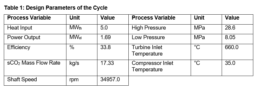
The design parameters of the sCO2 recuperated cycle are shown in Table 1. The recuperated configuration has been chosen for this study, due to its high thermal efficiency.
The proposed system has been modelled and simulated using the thermal-hydraulic system code ATHLET, which is part of the software AC2 developed by GRS [12]. ATHLET is based on a one- dimensional formulation of mass, momentum, and energy conservation equations. A complex system can be modelled by connecting basic fluid-dynamic elements, called thermo-fluid-dynamic objects (TFOs). The TFOs are composed of two basic elements: the control volumes (CVs) and their interconnections, called junctions. The conservation equations are spatially integrated using the control volume as the integration domain, whereas the junction is the integration domain for the momentum balances. This leads to CV- and junction-related quantities that represent the local physical state in a spatially averaged mode, sometimes called lumped parameter mode, and are time-dependent only. In the following sections, the modelling approaches for the cycle components are presented.
TURBOMACHINERY
The turbomachines, one compressor and one turbine with two stages each, have been modelled as lumped components using performance maps. The lumped parameter model provides the pressure difference Δp and the power P, which are source (compressor) or sink (turbine) terms to the momentum and the energy conservation equations respectively. The performance maps display the mass flow rate and the shaft speed on the x- and y-axis, and the efficiency, the isentropic enthalpy difference, or the pressure ratio on the z-axis. These maps are generated for only one fixed thermodynamic inlet condition, the design condition. To calculate the performance at different thermodynamic inlet conditions, a similarity approach is employed, transposing the performance maps to dimensionless maps. The full methodology is presented in [13]. After the dimensionless formulation, the performance maps are fitted using a bicubic spline approach. The generated coefficients are then provided as input to ATHLET. For the compressor, an additional step has been introduced.
Surge has shown to be a fundamental phenomenon to consider when modelling a compressor stage since it causes the flow through the entire compressor to be reversed intermittently [14,15]. The intermittent nature of the flow reversal creates large forces capable of damaging compressor bearings, seals, and other rotating elements. The surge limit is identified as the point at which the mechanical
input is insufficient to overcome the hydraulic resistance of the system. The distance from this point, the surge margin, may be defined as:

where m˙ op is the flow at the operating point and m˙ sp is the flow at the surge line for the same compressor speed line. The exact location of the surge line on the map can vary depending on the operating condition. As a result, a safety surge margin is established at 10÷20% above the stated flow for the theoretical surge line. For every operational point, the surge margin is computed to ensure the safe operations of the compressor and the cycle.
HEAT EXCHANGERS
In this cycle, there are three different heat exchangers. The first one is the heat pipe heat exchanger (HPHX): the heat generated in the reactor core is removed by the evaporator section of the heat pipes. The heat pipes transfer the heat to the sCO2 cycle through the HPHX, which connects the condenser section of the heat pipes to the power cycle. Currently, there is no practical design for such a heat exchanger, but the most promising solution would be to have a heat exchanger dedicated to every block of the core [4]: this would mean having six heat exchangers, in which the sCO2 should cool down 204 heat pipes. The configuration of the core gives the geometrical boundary conditions to the design of the HPHX. The second is the counter-current Printed Circuit Heat Exchanger (PCHE), which represents a promising solution as a recuperator, thanks to the compactness and efficiency of heat exchange [6,10]. The last heat exchanger in the sCO2 cycle removes the remaining heat from the sCO2 to the ambient air, which serves as the diverse ultimate heat sink (UHS). For this purpose, an air-cooled finned-tube heat exchanger is used. The fans used to cool the UHS on the air side are not modelled explicitly [16].
For the heat exchangers, the standard approach for modelling heat exchangers in ATHLET is employed
[13]: one representative channel, characterized by their representative flow areas and hydraulic diameters, is modelled and multiplied by the total number of channels. The representative channel is divided into several control volumes to account for local variations in the thermodynamic properties and the heat transfer coefficient. Flow friction factors and heat transfer coefficients are calculated using empirical correlations. For the sCO2, the heat transfer coefficient is calculated with the Gnielinski correlation, which is valid for Reynolds numbers between 2300 and 106 and Prandtl numbers from 0.6 to 2000 [17]. For the air side, the VDI correlation is used for staggered configuration [18].
VALVE
The standard valve in ATHLET can be located in every junction within a pipe. The impact on the thermal- hydraulics is an additional pressure drop ∆pvalve due to form losses in the valve in the momentum equation. In ATHLET, the form loss coefficient per unit squared area of the valve is defined as

where the subscript 0 indicates the fully open valve. The form loss coefficient ζ0 has been retrieved from
[18] and adapted to the flow area A. The relative valve form loss coefficient REZEV can be input as a table. In this case, a built-in table has been used, which increases the relative flow loss coefficient exponentially for decreasing the opening of the valve [12].
SYSTEM CONTROL STRATEGY
The system control strategy aims to achieve load following operations. For this purpose, it is essential to control and maintain key parameters such as the compressor inlet temperature (CIT) and the turbine inlet temperature (TIT) within a safe operational range. In addition, the shaft speed is kept constant at the design value.
CIT AND TIT CONTROL
The outlet condition of the sCO2 side in the UHS must be controlled to keep the compressor inlet in the desired operating range. In this study, the CIT is kept constant at 35 °C. The CIT control is performed by controlling the cold source. Technically, the speed of the fans should be the variable to be controlled. Due to the lack of a detailed model for the fans, for the simulations, the air mass flow rate was chosen instead as the controlled variable, based on the rationale that the volume flow rate is nearly proportional to the fan speed [16]. A Proportional Integral (PI) controller was used to control the air mass flow rate. The TIT is kept constant at its design value to prevent the temperature in the hot leg from increasing over the material’s safety limitations. This is done by controlling the heat input through a PI controller. The architecture of the control system for these two parameters is reported in Figure 1.

TURBINE THROTTLE VALVE
The turbine throttle valve has demonstrated promising results in regulating the power output of the sCO2 cycle [9–11]. The valve isoenthalpically expands the fluid entering the turbine, decreasing its temperature and pressure. This leads to a decrease in the turbine pressure ratio, which has a consequence of a lower mass flow rate and a lower turbine power production. This latter variable can be changed by adjusting the section of the valve. The opening or closing of the valve is controlled by an Integral (I) controller, based on the difference between the power produced and the one required by the consumers/grid. The location of the throttle valve in the cycle and the logic architecture of this control are shown in Figure 2.
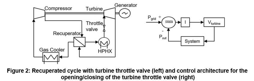
Figure 2: Recuperated cycle with turbine throttle valve (left) and control architecture for the opening/closing of the turbine throttle valve (right)
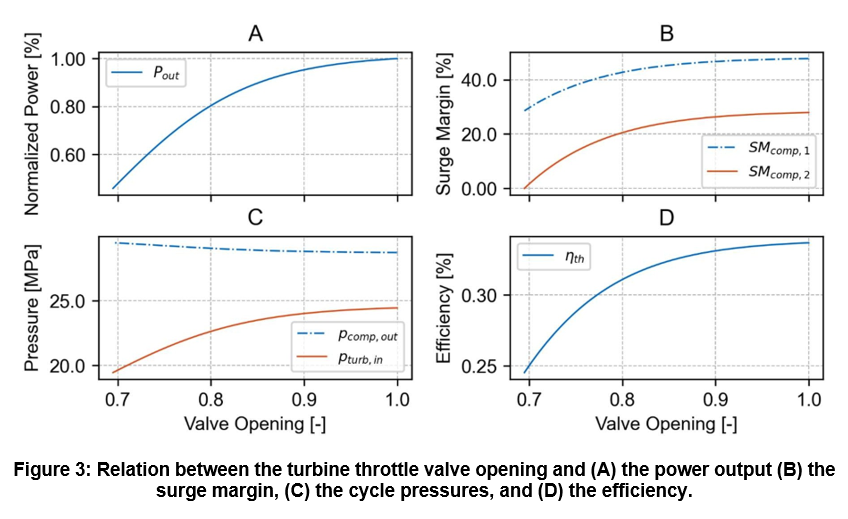
Before investigating a proper load following operation, the consequences and the limitations of the use of such control strategy need to be properly deepened. Changing the valve section leads to two main consequences that need attention. Firstly, the closing of the valve accumulates fluid at high pressure in the section preceding it. This could lead to excessive high pressure in the pipes [11]. Secondly, the closing of the valve reduces the mass flow rate flowing through the compressor. This could eventually lead to surge [10,11,19]. To investigate these aspects and understand the phenomenology of this process, the turbine throttle valve is gradually closed until failure of the system, deactivating the I controller. The results of this analysis are shown in Figure 3. It can be seen that by closing the valve, 46% of the nominal power can be reached before compressor surge occurs. Due to the differences in the performance maps, the surge appears in the second stage of the compressor. The valve closes until 70% circa, increasing the maximum pressure by 2.6%, making the final value manageable from the safety point of view. On the opposite, the pressure at the inlet of the turbine decreases until 20 MPa, causing the decrease in the turbine pressure ratio. This process efficiency shifts from 33.8% to 24.5%. With the current configuration, the system can be operated safely until 60% of the nominal power, which corresponds to a surge margin of 10%.
LOAD FOLLOWING PERFORMANCE
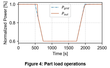
Considering the previous analysis, an example of transient behaviour involving a ramp down until 60% of the nominal power, followed by a ramp up to the nominal power, both at an aggressive rate of 10%/min, is simulated. The load following behaviour of the system is shown in Figure 4. Starting from the steady state condition, the power requested from the grid decreases drastically, reaching 60% of the nominal power in 240 s. It can be seen that the system adapts to the load request with some delay. This is because the controller of the opening of the valve has been set to be purely integral, eliminating the proportional part that is responsible for a prompt response. Attempts have been made to introduce the proportional gain, but this could not reach a significant value without destabilizing the system. However, after about 80 s, the power output matches quite closely the power demand. After 60% of the nominal power is reached, the power output is maintained constant for 1000 s. Then the nominal power is restored with the same transient. It can be seen that in this case, the delay in matching the power is negligible.
CONCLUSIONS
This study investigated the use of a turbine throttle valve for part load operations in a 5 MWth recuperated sCO2 Brayton cycle integrated with a Heat Pipe Cooled Micro Modular Reactor (MMR). For the investigated system, this strategy operates successfully down to 46% of the nominal power. To decrease the power further, countermeasures have to be taken to avoid surge at the compressor. An aggressive
load ramp, with a rate of 10%/min, until 60% of the nominal power was successfully simulated. The findings demonstrate that the turbine throttle valve constitutes a valid control strategy for such a system, thanks to its promptness. However, integration of other control strategies, such as compressor recirculation or inventory control, could extend the power reachable by the system, ensuring the safe operability of the compressor.
REFERENCES
- Zou and H.M. Subki, Advances in Small Modular Reactor Technology Developments, Austria (2022).
- H. Yan, C. Wang, and L.G. Li, „The technology of micro heat pipe cooled reactor: A review,
Annals of Nuclear Energy, 135 (2020).
- Testoni, A. Bersano, and S. Segantin, „Review of nuclear microreactors: Status, potentialities and challenges, Progress in Nuclear Energy, 138 (2021).
- R. Mcclure, D.I. Poston, V.R. Dasari, and R.S. Reid, Design of MegaWatt Power Level Heat Pipe Reactors (2015).
- W. Sterbentz, J.E. Werner, A.J. Hummel, J.C. Kennedy, R.C. O’Brien, A.M. Dion, R.N. Wright, and K.P. Ananth, Preliminary Assessment of Two Alternative Core Design Concepts for the Special Purpose Reactor, Idaho National Laboratories (2018).
- Ahn, S.J. Bae, M. Kim, S.K. Cho, S. Baik, J.I. Lee, and J.E. Cha, „Review of Supercritical CO2 Power Cycle Technology and Current Status of Research and Development, Nuclear Engineering and Technology, 47, pp. 647–661 (2015).
- Crespi, G. Gavagnin, D. Sánchez, and G.S. Martínez, „Supercritical carbon dioxide cycles for power generation: A review, Applied Energy, 195, pp. 152–183 (2017).
- T. White, G. Bianchi, L. Chai, S.A. Tassou, and A.I. Sayma, „Review of supercritical CO2 technologies and systems for power generation, Applied Thermal Engineering, 185 (2021).
- Wu, Y. Ma, C. Gao, W. Liu, J. Shan, Y. Huang, J. Wang, D. Zhang, and X. Ran, „A review of research and development of supercritical carbon dioxide Brayton cycle technology in nuclear engineering applications, Nuclear Engineering and Design, 368 (2020).
- A. Carstens, Control Strategies for Supercritical Carbon Dioxide Power Conversion Systems,
Massachusetts Institute of Technology, 2007.
- Wang, X. Wang, G. Shu, H. Tian, J. Cai, X. Bian, X. Li, Z. Qin, and L. Shi, „Comparison of different load-following control strategies of a sCO2 Brayton cycle under full load range, Energy, 246, 123378 (2022).
- Gesellschaft für Anlagen- und Reaktorsicherheit gGmbH, ATHLET 3.1 Model and Methods
(2022).
- Hofer, M. Buck, and J. Starflinger, „ATHLET extensions for the simulation of supercritical carbon dioxide driven power cycles, Kerntechnik, 84, pp. 390–396 (2019).
- Moisseytsev and J.J. Sienicki, Supercritical Carbon Dioxide Cycle Control Analysis, ANL (2008).
- Moore, K. Brun, and R. Kurz, „Tutorial on Centrifugal Compressor Surge Control, 47th Turbomachinery and 34th Pump Symposia, Huston, Texas, USA, September 17-20 (2018).
- Hofer, H. Ren, F. Hecker, M. Buck, D. Brillert, and J. Starflinger, „Simulation and Analysis of a Self-Propelling Heat Removal System using Supercritical CO2 at Different Ambient Temperatures, The 4th European sCO2 Conference for Energy Systems, Online Conference, March 23-24 (2021).
- Gnielinski, „Neue Gleichungen für den Wärme- und den Stoffiübergang in turbulent durchströmten Rohren und Kanälen, Forsch. Ing.-Wes., 41 (1975).
- Hofer, M. Buck, A. Cagnac, T. Prusek, N. Sobecki, P. Vlcek, and et al., Deliverable 1.2: Report on the validation status of codes and models for simulation of sCO2-HeRo loop (2020).
- J. Sienicki and A. Moisseytsev, Status Report on the Small Secure Transportable Autonomous Reactor (SSTAR)/ Lead-Cooled Fast Reactor (LFR) and Supporting Research and Development, ANL (2006).
ACKNOWLEDGEMENTS
The presented work was funded by the German Federal Ministry of Education and Research (BMBF, project no. 02NUK074A) on basis of a decision by the German Bundestag.
0 Comments