Daniel Eckert, Fabian Weyermann, Norman Dünne, Andreas Schaffrath
Gesellschaft für Anlagen- und Reaktorsicherheit (GRS)
Boltzmannstr. 14, 85748 Garching, Germany daniel.eckert@grs.de, fabian.weyermann@grs.de, norman.duenne@grs.de,
Jörg Starflinger
Institut für Kernenergetik und Energiesysteme (IKE) Pfaffenwaldring 31, 70569 Stuttgart, Germany joerg.starflinger@ike.uni-stuttgart.de
SUMMARY
Heat pipe-cooled micro modular reactors (HP-MMRs) are very small and transportable nuclear reactors, which are being developed to provide energy to remote areas. They use passively working liquid metal- filled heat pipes (HP) for core cooling. A HP utilises phase transition of a fluid and capillary pumping for transferring heat. The thermal hydraulics code ATHLET is currently being improved for simulations of HP-MMRs. A fluid property package for potassium has recently been implemented. This article presents a first HP model, which covers capillary transport, friction, and phase change, and the results of an operating HP. The predicted phase velocities fit well with analytical results. The liquid is sub-cooled in the condenser section and super-heated in the evaporator section in agreement with theoretical predic- tions during stable HP operation.
KEYWORDS
Thermal Hydraulics, Heat Pipe, ATHLET
INTRODUCTION
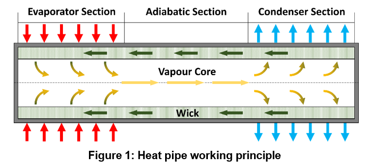
Micro modular reactors (MMRs) are a subgroup of small modular reactors with a low power output, typically up to 10 MWel, designed for off-grid or micro-grid operation [1]. Heat pipe-cooled MMRs (HP- MMR) utilise numerous, passively working, alkali metal-filled heat pipes (HP) for reliable core heat removal [2 – 4]. They have a solid core design, avoid high pressures, and operate at high temperatures enhancing thermal efficiency of the energy conversion unit. A Brayton cycle based on air or supercritical CO2 is suited due to its high reliability and compactness [2]. The HPs are partly integrated into the solid core block, and they transfer heat to the energy conversion unit through a heat exchanger during regular operation. In case of decay heat removal or emergency cooling, heat is transferred to the ambient air through a second heat exchanger. For reference design, see [5]. A HP is a two-phase device which utilises phase transition of a fluid for transferring heat [6,7]. It consists of a sealed pipe, a wick structure, and a heat transfer fluid (see Figure 1). The reactor’s heat input in the evaporator section evaporates liquid. The vapour flows from the evaporator section to the condenser section within the heat exchangers due to a pressure gradient. Condensation happens there, and heat is removed to a heat sink. The transport of the liquid back to the evaporator section is driven by capillary forces. The working fluid must be selected based on the operation temperature of the HP. Typical high-temperature HP fluids used in HP-MMR designs are sodium or potassium.
The HP-MMR concepts are often mobile, modular systems being assembled and fuelled in a factory and transportable by truck or air transport to remote locations [1, 2]. There is currently an interest in the application of mobile HP-MMR systems for the energy supply of remote settlements or military bases, e.g., in North America [8].
Numerical tools enable the safety assessment and performance analysis of HP-MMRs [9,10]. The one- dimensional code THROHPUT can be used for the analysis of liquid metal HPs during operation and start-up [11]. It is able to consider solid, liquid, and vaporous working fluid as well as non-condensable gases. HPTAM is a two-dimensional HP analysis software that considers axial and radial flow in the vapour core and the wick [12]. SOCKEYE is a one-dimensional HP analysis application based on the thermal hydraulics code RELAP-7, which is currently in development [13]. Shi et al. [14] developed a one-dimensional, three-field HP model, which accounts for vapour, liquid film, and liquid droplets for consideration of possible entrainment.
GRS and IKE Stuttgart cooperate within the MISHA project for safety analysis of HP-MMR. Part of the project is the extension of the thermal hydraulics code ATHLET [15] for the simulation of liquid metal- filled HPs. A fluid property package for potassium covering the properties of the liquid and the vapour has recently been implemented [16]. It is available from the current ATHLET version 3.4.0 [17]. A first HP model is currently being developed.
METHODS
ATHLET employs a transient, one-dimensional, two-fluid model with fully phase-separated conservation equation for mass, momentum, and energy of each the liquid and the vapour [18]. The solution variables are the liquid temperature 𝑇𝑙 , the vapour temperature 𝑇𝑣 , the liquid volumetric flow rate 𝑤𝑙𝐴, the vapour volumetric flow rate 𝑤𝑣𝐴, the pressure 𝑝, and the mass quality 𝑥.
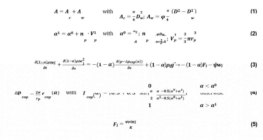
The HP model assumes the liquid to be present in the wick structure at the cylindrical HP wall and at the wick inner surface if the wick is oversaturated. The total flow area 𝐴 (equation 1) is based on the cross section of the vapour core 𝐴𝑐 and the open flow area in the wick structure 𝐴𝑤 with the pipe diameter
𝐷, the inner wick diameter 𝐷𝑤 and the porosity 𝜑. The void thresholds correlating either with a flat interface (𝛼0) or a maximum bent interface (𝛼1) are defined in equation 2. Here, 𝑛𝑝 is the volumetric
|
pore density at the inner wick face, 𝑉1 is the hemispherical volume of a pore.
To model the capillary-driven transport of the liquid through the wick, the liquid momentum equation (see equation 3) considers 𝑝, the capillary pressure difference ∆𝑝𝑐𝑎𝑝, the gravity force 𝜌𝑙𝑔, the friction term 𝑓𝑙, and the momentum flux due to the phase change 𝜓. Interfacial friction is neglected. The vapour momentum equation (not shown explicitly) is similar but does not include the ∆𝑝𝑐𝑎𝑝 term.
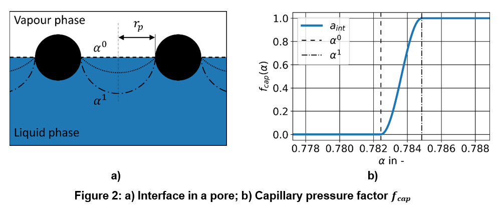
∆𝑝𝑐𝑎𝑝 (equation 4) is based on the surface tension 𝜎, the effective pore radius 𝑟𝑝, and a factor 𝑓𝑐𝑎𝑝, which expresses the shape of the interface based on the void 𝛼 as pictured in Figure 2a. 𝑓𝑐𝑎𝑝 is equal to zero
if the interface is flat (𝛼 ≤ 𝛼0) and it is equal to one if the interface is bent to its maximum (𝛼 ≥ 𝛼1). In between, a smooth transition is realised with a sinus-based expression (see Figure 2b).
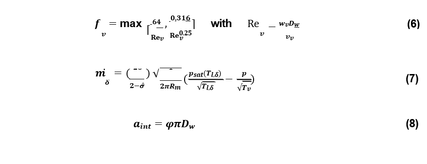
In the wick, a low liquid velocity and a laminar liquid flow can be expected [6]. The respective pressure drop term 𝐹𝑙 (equation 5) is based on the permeability of the wick structure 𝐾 and liquid viscosity 𝜇𝑙. The pressure drop in the vapour phase is based on a Darcy friction factor 𝑓𝑣 (see equation 6). The laminar and the turbulent case are considered. Here, 𝑅𝑒𝑣 is the Reynolds number and 𝑣𝑣 is the vapour kinematic viscosity.
The phase change mass flux is predicted based on the Schrage equation (equation 7) with the specific gas constant 𝑅𝑚, the vapour pressure 𝑝𝑠𝑎𝑡, the temperature of the free liquid film surface 𝑇𝑙,𝛿 and the accommodation coefficient 𝜎̂ [6,19]. The interfacial area per unit length 𝑎𝑖𝑛𝑡 (equation 8) is approximated by taking the free inner surface of the cylindrical wick structure.
The assumptions are constant heat transfer coefficient between the liquid film and the wall, azimuthal symmetry, neglecting interfacial energy, and neglecting the impact of wick roughness and radial vapour flow on the axial vapour pressure drop. The porosity 𝜑 is assumed to be valid as a surface porosity. A radial liquid temperature gradient is neglected, and the liquid temperature is used in the phase change model (𝑇𝑙 = 𝑇𝑙,𝛿 ).
RESULTS
The HP model was tested based on a generic, cylindrical HP design shown in Figure 3. The HP parameters and steady operation conditions are summarised in Table 1. There is enough liquid for saturating the wick and maintaining a small reservoir at the HP bottom. The evaporator and condenser sections are heated or cooled radially and homogeneously. Assumptions are no heat transfer through the HP end caps, neglectable thermal conductivity of the wick, and no axial heat conduction in the liquid phase. The HP object was nodalised with 42 equally sized control volumes.
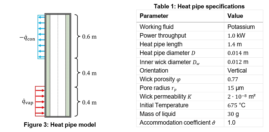
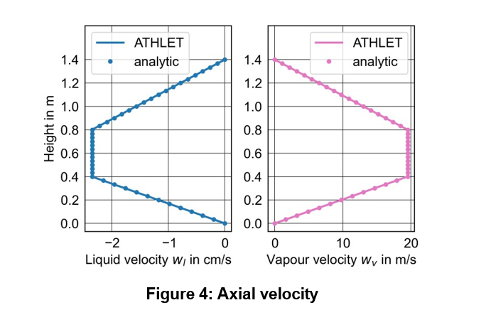
Figure 4 compares the simulated axial velocities with an analytical solution based on equation 9 with the enthalpy of vaporisation ℎ. Due to the homogeneous heating and cooling, the phase velocities 𝑤v and 𝑤l change linearly in the corresponding HP sections. The simulation result matches the analytical solution.

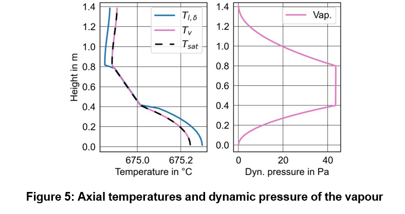
The axial vapour temperature, the free liquid film surface temperature, and the dynamic vapour pressure are presented in Figure 5. Since the heating and the cooling are equal, the total energy does not change, and the temperatures are close to the initialisation value. The vapour temperature gradient with respect to the altitude is negative in the evaporator and in the adiabatic section. As the vapour temperatures are very close to the saturation temperature 𝑇𝑠𝑎𝑡, the geodetic pressure and the friction pressure drop cause the decrease of static pressure and saturation temperature in flow direction. In the evaporator section, the flow acceleration causes the additional reduction of the pressure gradient (see dynamic pressure of the vapour). In the condenser section, on the other hand, there is a positive vapour temperature gradient due to pressure recovery.
There are differences between 𝑇𝑣 and 𝑇𝑙,𝛿 in the evaporator and the condenser, where the liquid is superheated in the evaporator and subcooled in the condenser. At stable HP conditions, there is no nucleate boiling in the liquid film but free surface vaporisation. Heat conduction in the liquid results in a radial temperature gradient and superheated liquid.
CONCLUSION
In the joint project MISHA of GRS and IKE, the thermal hydraulics code ATHLET is being improved for the safety analysis of HP-MMR. The properties of potassium have been implemented recently into ATHLET and are available with the current program version 3.4.0. A first heat pipe model was presented in this work. Results of a simulation were shown and match well with theoretical predictions for the velocities. The predictions of the free liquid film surface temperature and the vapour temperature are reasonable, and their trends are linked to local vapour pressure. Further work is required for improving the ATHLET heat pipe models. This includes detailed modelling of the interfacial area, and the radial
heat transfer through the liquid and the wick each based on geometric HP properties. Later affects significantly the overall thermal resistance of a HP at the regarded operation condition. Furthermore, the heat pipe model is to be improved for considering axial heat conduction in the liquid phase, and for modelling the evaporator pool. The validation of the final ATHLET heat pipe model is planned based on upcoming experiments at IKE.
REFERENCES
- “Advances in Small Modular Reactor Technology Developments: A Supplement to: IAEA Advanced Reactors Information System (ARIS),” International Atomic Energy Agency (IAEA) (2022).
- H. Yan, C. Wang, and L. G. Li, “The Technology of Micro Heat Pipe Cooled Reactor: A Review,” Annals of Nuclear Energy, Vol. 135, p. 106948 (2020).
- Bo, X. Shunhao, W. Bin et al., “Review of Recent Research on Heat Pipe Cooled Reactor,”
Nuclear Engineering and Design, Vol. 415, p. 112679 (2023).
- P. Guillen, “Review of Passive Heat Removal Strategies for Nuclear Microreactor Systems,”
Nuclear Technology, 209.sup1, pp. 1–20 (2022).
- W. Sterbentz, J. E. Werner, A. J. Hummel et al., “Preliminary Assessment of Two Alternative Core Design Concepts for the Special Purpose Reactor,” INL/EXT-17-43212, Idaho National Lab.(INL), Idaho Falls, ID (United States) (2018).
- Faghri, Heat Pipe Science and Technology, Second Edition, Global Digital Press, Columbia, Mo. (2016).
- D. Dunn and D. A. Reay, Heat pipes, 4. ed., Pergamon, Oxford (1994).
- H. Jackson and P. Sabharwall, “Foreword: Special Issue on the U.S. Department of Energy Microreactor Program,” Nuclear Technology, Vol. 209 (sup1), pp. iii–v (2023).
- Mueller and P. Tsvetkov, “A Review of Heat-Pipe Modeling and Simulation Approaches in Nuclear Systems Design and Analysis,” Annals of Nuclear Energy, Vol. 160, p. 108393 (2021).
- Tian, C. Wang, K. Guo et al., “A Review of Liquid Metal High Temperature Heat Pipes: Theoretical Model, Design, and Application,” International Journal of Heat and Mass Transfer, Vol. 214, p. 124434 (2023).
- L. Hall, “Transient Thermohydraulic Heat Pipe Modeling: Incorporating THROHPUT into the CÆSAR Environment,” AIP Conference Proceedings, Albuquerque, New Mexico (USA), 28 January 2003, Vol. 654, pp. 106–113 (2003).
- -M. Tournier and M. S. El-Genk, “A Heat Pipe Transient Analysis Model,” International Journal of Heat and Mass Transfer, Vol. 37 (5), pp. 753–762 (1994).
- E. Hansel, R. A. Berry, D. Andrs et al., “Sockeye: A One-Dimensional, Two-Phase, Compressible Flow Heat Pipe Application,” Nuclear Technology, Vol. 207 (7), pp. 1096–1117 (2021).
- Shi, Y. Liu, I. Yilgor et al., “A Two-Phase Three-Field Modeling Framework for Heat Pipe Application in Nuclear Reactors,” Annals of Nuclear Energy, Vol. 165, p. 108770 (2022).
- “ATHLET 4.0 Program Overview,” Gesellschaft für Anlagen- und Reaktorsicherheit (GRS) gGmbH (2023).
- Eckert, “Implementation of Potassium as a Working Fluid into ATHLET,” Technical Report TB- ECD-01-23, Gesellschaft für Anlagen- und Reaktorsicherheit (GRS) gGmbH (2023).
- Schöffel, New Models and Features in ATHLET 3.4.0, Gesellschaft für Anlagen- und Reaktorsicherheit (GRS) gGmbH (27.11.2023).
- Schöffel, A. Di Nora, D. Eckert et al., “ATHLET 3.4.0 Models and Methods,” GRS-P-1/Vol. 4 Rev. 8, Gesellschaft für Anlagen- und Reaktorsicherheit (GRS) gGmbH (2023).
- Vaartstra, Z. Lu, J. H. Lienhard et al., “Revisiting the Schrage Equation for Kinetically Limited Evaporation and Condensation,” Journal of Heat Transfer, Vol. 144 (8), p. 80802 (2022).
ACKNOWLEDGEMENTS
The MISHA project is sponsored by the German Federal Ministry of Education and Research (BMBF) based on a decision by the German Bundestag under the project number 02NUK074.
0 Comments