Lorie Meunier
Hochschule Mannheim, Mannheim University of Applied Sciences Paul-Wittsack-Str. 10, 68163 Mannheim
Lotte Lens, Niklas Heiß, U. W. Scherer
Hochschule Mannheim, Mannheim University of Applied Sciences Paul-Wittsack-Str. 10, 68163 Mannheim
l.lens@hs-mannheim.de; n.heiss@hs-mannheim.de; u.scherer@hs-mannhem.de
SUMMARY
Characterisation of irradiated, thus activated graphite samples is mandatory before any decontamination steps can be developed. Various non-destructive and destructive measurement techniques are used for it. The accurate determination of the activity of γ-emitters is conducted by gamma ray spectrometry with high purity germanium (HPGe) detectors, while electronic autoradiography allows the mapping of the β- emitter distribution in order to verify the homogeneity inside of the samples. Since the two key radionuclides of the project being tritrium (H-3) and radiocarbon-14 (C-14), are both pure beta emitters, an additional quantification method is required. The activities are determined by Liquid Scintillation Counting (LSC), after a destructive sample preparation using an oxidizer.
KEYWORDS
i-graphite, characterization, oxidizer, LSC, autoradiograph
INTRODUCTION
Graphite is a commonly used material in nuclear reactors, such as in construction material, moderators, reflectors and fuel sleeving material. Over time the graphite and its impurities are activated due to neutron capture processes. Based on the reactor type, the graphite manufacturing process, the operating time, the radioisotopes to be found in the samples may differ. Globally, irradiated reactor graphite (i-graphite) present a substantial challenge, amounting to approximately 250,000 tons, with Germany contributing a relatively modest 2,000 tons, primarily from research reactors [1]. The contaminated wastes are to be potentially disposed in the final repository KONRAD. Due to the strict guidelines in KONRAD, concerning maximum allowable activities of radionuclides, it is important to know inventories and activities. However, there is a lack of information about those data. To address this issue, simulations can be performed to give a first assumption on the inventory but nevertheless experimental characterisation is necessary. For further details on the simulation methodology, a paper by M. Klink [2] and a poster by N.Heiß are provided. For further information on the general problematic of irradiated graphite waste, a paper and a presentation are provided by L. Lens [3].
In irradiated graphite samples, ß- and g– emitters can be found. Therefore, special analytical techniques need to be used to identify and quantify the different radionuclides. In this work different analytical techniques are used for the characterisation of the irradiated graphite samples. For the project, non- destructive and destructive measurement methods are used for the characterisation. The non- destructive measurement methods include measurements with high purity Germanium (HPGe) detectors, and an autoradiographic system. The destructive method involves measurements using
Liquid Scintillation Counting (LSC). As this requires sample preparation using an oxidizer, resulting in complete destruction of the matrix.
This work focuses on the development of a methodology for the characterisation of i-graphite, while applying the above mentioned analytical techniques.
METHODS
NON-DESTRUCTIVE MEASUREMENT METHODS
Gamma ray spectrometry with a HPGe detector is a standard measurement technique used in nuclear industry and research to detect g-emitters. This technique has several advantages: being non- destructive due to the strong penetration of the gamma ray through matter, little sample preparation is needed, and any geometry can be measured.
Due to the fact that every sample has its own geometry, and the efficiency of the detector strongly depends on the geometry, efficiency curves are required for the determination of accurate activities. This is done with a multi-nuclide standard with energies ranging from 60 keV to 1836 keV used in different geometries. Data measured for different geometries e.g. Marinelli Beaker, cylindrical bottle etc., are compared with results provided by simulation software such as LABSOCS [4], Efftran [5], Mefftran
[6] and FLUKA [7] [8] [9]. These codes allow the prediction of the efficiency curves of any geometry. Geometry is just one of the parameters that may vary among samples.
Previous simulation and experimental characterisation were performed before dismantling the FiR1 TRIGA Reactor in Finland. Typical g-emitters were found in the irradiated graphite such as Co-60, Ba- 133 and Eu-152 [10]. Those g-emitters are also expected to be found in the studied graphite samples of the project. Indeed, the radionuclide inventory can be estimated when comparing similar reactors. The presence of gamma ray emitters is relevant for the dose rate which may limit the handling procedures.
However, this technique is suitable only for g-emitters, while the focus of the project lies on two specific radionuclides: tritium and carbon-14, both pure β-emitters. As the range of these very low energy beta particles is extremely short, quantifying their activities requires a destructive measurement method. The sampling step for the destructive method requires to know if the nuclides within the sample are homogeneously distributed or not. To do so, a modern real-time autoradiographic system is used.
Mapping beta radiation patterns provides crucial insights into the spatial distribution of nuclide emissions, contributing to a nuanced understanding of the waste material. The electronic autoradiographic method, as outlined by Baier [11] and Poncet et al. [12], allows us to comprehensively characterize beta nuclide emissions within irradiated reactor graphite and is employed for a detailed investigation of radionuclide distribution and identity within reasonable statistical limits. This involves mapping the spatial distribution of radionuclides on a two-dimensional plane, providing precise insights into nuclides emitting selective energy ranges. The identification and quantification of β-emitting nuclides, such as H-3 and C-14, are determined using predetermined parameters for a comprehensive analysis.
Studies by Ghosh [13] revealed that a portion of the C-14 activity may be situated near the surface, while the other part is usually homogeneously distributed in the volume. Notably, other (metallic) radionuclides often form ‚hotspots‘, indicating highly heterogeneous distribution patterns.
DESTRUCTIVE MEASUREMENT METHODS
Since the key nuclides H-3 and C-14 are pure beta emitters, they cannot be measured using HPGe detectors. Instead, LSC is used for the quantitative determination of their activity. Prior to conducting measurements with the LSC, a sample preparation is necessary using an oxidizer. To ensure representative sampling, it is crucial that the activity in the sample is uniformly distributed within the matrix. This homogeneity is ensured by the autoradiograph, as described above. The oxidization step involves burning the graphite samples in a continuous stream of oxygen to convert the graphite into CO2 and subsequently capturing the gases in suitable solutions. Following this process, the cocktail solution can be measured using the LSC.
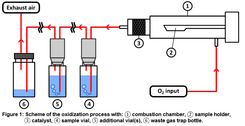
Figure 1, shows the scheme of the oxidation process. For this purpose, an industrial oxidizer is used, which has been modified and optimized to suit the applicable measurement requirements. The individual process steps are described in more detail in the following paragraph. The combustion tube is made from quartz glass and consists of two parts: the actual combustion chamber ① in which the sample is burned and the downstream catalytic converter ③ that will be described later. The sample holder ②, or ladle is automatically inserted into the combustion chamber by the system. The system holds a total of 6 ladles, which enables us either a higher sample throughput or a higher sensitivity with a multi-ladle setting. Since the possible sample amount of graphite is limited (<50 mg), the multi-ladle setting allows the combustion of several samples into the same vial. This is particularly advantageous for samples with very low activities, as it increases both the total mass of the combusted sample and the accumulation of associated activity within the same vial. Due to the small sample quantities, it is important that the activity in the sample is homogeneously distributed, as already mentioned. The catalyst ③ is necessary to convert the CO produced by incomplete combustion to CO2. Given that the liquid absorber in the sample vial ④ selectively binds only CO2, it contributes to reducing yield losses and consequently increases the recovery rate. Other nuclides, like tritium, can be retained in appropriate absorber solutions using optional additional downstream vials ⑤, allowing an assessment of the overall activity of the sample. Additionally, one or more vials can be filled with the same solution as in ④ to enhance the recovery rate of CO2. In the final step, a waste gas trap bottle ⑥ ensures that no radionuclides reach the exhaust air. Subsequently, the exhaust air stream is directed through a filter to guarantee that absolutely no radionuclides is released to the environment.
To ensure compliance with the manufacturer’s specifications, tests with the oxidizer were conducted using radionuclide standards to determine recovery rates, which are particularly crucial, as the count rate measured by the LSC needs correction based on these. This correction is essential for drawing accurate conclusions about the actual activity of the sample. These tests must be performed for each individual ladle setting and all multi-ladle settings, as recovery rates depend on the matrix and the number of ladles per vial.
LSC has been a widely used method for the detection and quantitative measurement of radioactivity since the 1950s and is still a popular instrument for analysing radionuclides in scientific research. LSC is mainly used to investigate nuclides that emit alpha and beta particles [14]. In Liquid Scintillation Counting, radioactivity is detected by creating photons through ionizing radiation. A scintillation cocktail, containing fluorescent molecules, absorbs radiation energy and emits visible light, with a wavelength of 375-430 nm [14] during the scintillation process. Light intensity depends on the type and original energy of the nuclear decay. Higher decay energies result in higher light intensity. The photons are detected by one or more photomultiplier tubes (PMT). The LSC used in this project has three PMTs, which are aligned at a 120° angle to each other and thus makes it possible to determine the counting efficiency using the triple-double coincidence ratio (TDCR), where the value is always between 0 and 1, where 1 stands for 100 % counting efficiency and 0 for 0 %. A double coincidence signal occurs when photons
created by one beta particle are detected by two out of the three PMTs within a specified time frame (coincidence time), unique to each device. Consequently, three potential double coincidence signals (AB, BC, and AC) can be obtained. On the other hand, a triple coincidence signal (ABC) is produced when some of these photons are detected simultaneously by all three PMTs within the established coincidence time [14]. This parameter is very useful for LSC measurements, as it allows the counting rates to be converted directly into activities. However, it should be noted that the counting efficiency for β-particles depends on their energy. For β-particles with decay energies above 100 keV, e.g. for C-14 with a decay energy of Emax=156.5 keV [15], the counting efficiency is between 80-100 %. For decay energies below 100 keV, e.g. for H-3 with a decay energy of Emax=18.6 keV [16], the counting efficiency is between 10-60 % [14]. Due to the different counting efficiencies, it is therefore important to separate the H-3 from the C-14, as both nuclides have different counting efficiencies and thus the calculated activity would not be accurate. This is the reason why, in the oxidization step, the C-14 is captured in the first vial (④ in Fig. 1) and the H-3 is captured in additional downstream vial (⑤ in Fig. 1). This has two advantages: firstly, it makes it possible to measure the two nuclides separately and draw conclusions on their actual activity based on their counting efficiency and secondly, there is no need to convert the gross β-spectrum into two individual spectra for each individual nuclide. The measurement protocols used for the LSC are all in accordance with DIN ISO 11929 [17].
CONCLUSION AND SCOPE
The results obtained with the developed methodology show promising approaches for the comprehensive characterization and subsequent decontamination of irradiated graphite samples. The combination of non-destructive techniques, including gamma-ray spectrometry and autoradiography, and the application of destructive methods such as sample oxidation followed by LSC leads to a detailed understanding of the radionuclide inventory and its distribution in the samples.
To this date, only one type of sample (coming from the TRIGA reactor in Mainz) is in the state of analysis and the methodology is developed based on these samples. Therefore, a method validation will need to be performed for samples from various other reactors. We hope to draw a relation between the experimental results and the simulations in order to optimize the future characterisation and the following decontamination procedures.
REFERENCES
[1] | IAEA-TECDOC1790, “Processing of Irradiated Graphite to meet Acceptance Criteria for Waste Disposal”Vienna, (2010). |
[2] | M. Klink, “Estimating of radionuclides inventory and activites of irradiated reactor graphite using the Monte-Carlo based programm FLUKA,” Proceedings Kerntechnik 2024, Leipzig, (2024). |
[3] | L. Lens, “Characterization and decontamination of irradiated reactor graphite-Overview,” Proceedings Kerntechnik 2024, Leipzig, (2024). |
[4] | I. Mirion Technologies, “Technical Advantages of ISOCS./LabSOCS,” (2022). |
[5] | T. Vidmar, “EFFTRAN—A Monte Carlo efficiency transfer code for gamma-ray spectrometry,” Nuclear Instruments and Methods in Physics Research, vol. 550 (no. 3) pp. 603-608, (2005). |
[6] | Nikolic JK, Rajacic M, Todorovic D, Vidmar T, “The first experimental test of the MEFFTRAN software on HPGe detector calibration for environmental samples,” J Environ Radioact, pp. 191- 196, (2016). |
[7] | G. Battistoni, et. Al., “Overview of the Fluka code,” Annals of Nuclear Energy , (2015). |
[8] | e. A. C. Ahdida, “New capabilities of the Fluka multi-purpose code,” in Frontiers in Physics, vol. 9, (2022). |
[9] | V. Vlachoudis, “Flair: A powerful but user friendly graphical interface for Fluka,” (2009). |
[10] | A. Räty, “Activity Characterization Studies in FiR 1 TRIGA Research Reactor Decommissioning Project,” (2016). |
[11] | M. Baier, “Autoradiographic investigations of reactor graphite,” Master thesis, (2011). |
[12] | L. B.Poncet, “Method to assess the radionuclide inventory of irradiated graphite waste from gas- cooled reactors,” in J Radioanal Nucl Chem, (2013). |
[13] | S. Ghosh, “Systematic autoradiographic investigation of irradiated reactor graphite,” Master thesis, (2013). |
[14] | M. F. L’Annunziata, “Chapter 7: Liquid Scintillation,” in Handbook of radioactivity analysis, (2020). |
[15] | Bé M.-M., et Al., “Table of Radionuclides,” in Monographie BIPM-5, vol. 7, Bureau International des Poids et Mesures, (2013). |
[16] | Bé M.-M., et Al., “Table of Radionuclides,” in Monographie BIPM-5, vol. 3, Bureau International des Poids et Mesures, (2006). |
[17] | “DIN EN ISO 11929-1:2021-11, Bestimmung der charakteristischen Grenzen (Erkennungsgrenze, Nachweisgrenze und Grenzen des Überdeckungsintervalls) bei Messungen ionisierender Strahlung – Grundlagen und Anwendungen – Teil 1: Elementare Anwendungen,” (2019). |
ACKNOWLEDGEMENTS
The project is supported by the federal ministry for education and research [15S9442]. A special thanks to the staff of TRIGA Mainz and JEN Jülich for collaborating and providing us with samples and information.
0 Comments