Ruggero Meucci
Institute of Nuclear Technology and Energy Systems (IKE) – University of Stuttgart Pfaffenwaldring 31, 70569, Stuttgart, Germany
Ruggero.Meucci@ike.uni-stuttgart.de
Rudi Kulenovic, Jörg Starflinger
Pfaffenwaldring 31, 70569, Stuttgart, Germany Rudi.Kulenovic@ike.uni-stuttgart.de, Joerg.Starflinger@ike.uni-stuttgart.de
SUMMARY
Recent years have confirmed a growing interest in Small Modular Reactors (SMRs) and Micro Modular Reactors (MMRs) for their potential to boost energy supply reliability and reduce carbon emissions in isolated power grids. MMRs employ high-temperature heat pipes using liquid metal (e.g. potassium or sodium) as working fluid to efficiently extract heat from the core. The MISHA project, funded by BMBF, aims to enhance expertise on MMRs utilizing heat pipes as primary heat transfer systems. It involves constructing and testing full-size nuclear-grade high-temperature heat pipes and a Heat Pipe Tester (HPT). The HPT, designed with modular flexibility, facilitates testing of heat pipes of varying lengths and diameters under different conditions, enabling comprehensive performance evaluation and advancing the understanding of heat pipe efficiency in diverse applications.
KEYWORDS
Heat Pipe, Potassium, Passive Heat Exchange, SMR, MMR
INTRODUCTION
In recent years there has been a increasing interest in Small Modular Reactors (SMRs) and Micro Modular Reactors (MMRs) due to their potential to enhance significantly the reliability of energy supply while concurrently reducing carbon emissions in isolated power grids. These innovative reactor designs offer scalable and flexible solutions, making them well-suited for diverse applications ranging from powering remote communities to energy-intensive industrial facilities. In particular, MMRs are intended to be deployed rapidly in remote locations or in emergency situations, making them particularly suitable also for space applications. This is why reactors such the Kilopower reactor [1] and the eVinci reactor
[2] have been designed. These MMRs utilize high-temperature heat pipes to efficiently extract heat from the reactor core.
Heat pipes are remarkable passive heat transfer devices designed to extract efficiently large amounts of heat while minimizing thermal losses. Essentially, they consist of closed pipes with a capillary structure on their inner surface and are partially filled with a working fluid. When heat is applied to one end of the pipe, the fluid evaporates and travels to the opposite end, where it condenses, releasing heat. The liquid then returns to the evaporation zone through the capillary structure. With a wide range of possible working temperatures, spanning from -200 °C to over 2,000 °C, heat pipes offer versatile thermal management solutions.
Commonly utilized to dissipate heat from compact yet powerful heat sources, such as high-performance microchips, heat pipes play a crucial role in maintaining optimal operating conditions. Moreover, as previously mentioned, they find application in emerging technologies like micro nuclear reactors [3], where efficient heat transfer is essential for safe and reliable operation. In fact, heat pipes provide a fully passive cooling system, a feature more and more common in Gen IV reactor designs.
MISHA Project
The present work is realised in the framework of the joint research project MISHA (project partner IKE
and GRS). The project, funded by BMBF, aims to improve the expertise and knowledge on MMRs that use heat pipes as a primary heat transfer device in the cooling system. One of the objectives of the project is to realize and test a few full size, nuclear grade high-temperature heat pipes. Furthermore, the test results will be used for the further development and validation of the GRS nuclear safety code system ATHLET.
EXPERIMENTAL SETUP
Achieving the project’s targets implies the construction of both some heat pipe prototypes and a experimental test set-up, subsequently called Heat Pipe Tester (HTP). The following paragraphs describe the design and the ongoing construction of the heat pipes and the HPT.
Heat Pipe Prototypes
High-temperature heat pipes typically use potassium or sodium as working fluid (even though also NaK and Li can be used). In the MISHA project all pipes will be filled with potassium with only one exception, as reported in Table 1, of the first “test” heat pipe. Theoretically potassium allows working temperatures ranging from 500 °C to 1100 °C [4] while sodium allows temperatures from 600 °C to 1200 °C [4]. However, the usual working temperature of both heat pipes is around 800°C. Both fluids are chemically reactive and highly corrosive. Hence, the range of structural materials whose mechanical properties do not deteriorate at high temperatures and that have high corrosion resistance is limited: SS316, Inconel 600 [4] and Haynes 230 [1]. Inconel 600 has been proven to resist better to corrosion and high temperatures altogether. Hence it has been chosen as structural material despite its higher cost.
At least three heat pipe configurations with different inner shapes will be tested as depicted in Figure 1:
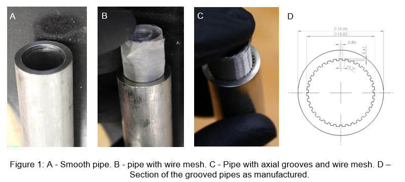
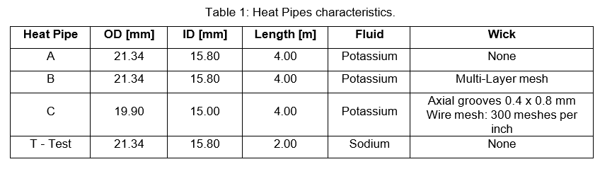
Case A is a closed thermosiphon made from a smooth pipe and will act as a reference to evaluate the effects of different wicks in the pipe of case B and C. Multiple layers of a wire mesh will create a capillary structure both in case B and C. However, in case C the wick lays on an axially grooved surface (Figure 1D). Such grooves will act as arteries that should facilitate the liquid flow back to the evaporator. In addition to those heat pipes a shorter test heat pipe will be manufactured. It will be used to test the manufacturing, the filling and the sealing procedures as well as the proper functioning of the HPT. The geometrical properties of all heat pipes are summarized in Table 1.
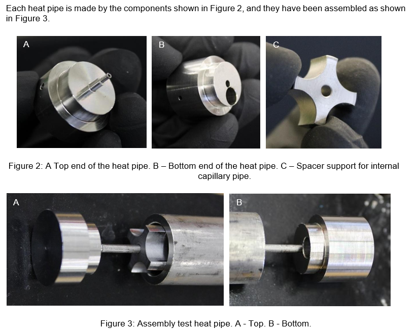
All weldings have been realized by electron beam welding as suggested in [4] since this welding technique provides the most accurate and reliable sealing.
A capillary pipe (ID/OD 1.50/2.50 mm) is internally fixed along the heat pipe axis. This capillary can host any measurement system that can fit inside it. At first a thermocouple will be used to measure locally the heat pipe inner temperature. Later on, the thermocouple will be replaced by an optic fibre temperature sensor able to measure temperatures every 5 mm, hence providing a axial temperature profile [7][8]. The capillary pipe is quite flexible, so it has to be fixed inside the heat pipe. Therefore, spacer supports (see Figure 2C resp. 3A) are placed every 40 cm in the heat pipe. In Figure 4 the assembled test heat pipe is shown.

Once mechanically assembled the heat pipe has to undergo the following procedures:
- Outgassing: The heat pipe is connected to a vacuum pump and leak tests are Air is removed from the pipe.
- Filling: The working fluid is inserted in the heat pipe. Since both sodium and potassium oxidise quickly if in contact with air, the procedure must be carried out in an inert argon At the end of the procedure the pipe is filled with the working fluid and argon. It is temporary closed by a SS316 valve.
- Sealing: the pipe is put in a vacuum chamber; the valve is opened and all argon is removed from the heat pipe. The filling pipe is locally heated up to the melting point of about 1430 °C, clamped and sealed permanently.
Each procedure requires an ad-hoc facility that is currently being built.
Heat Pipe Tester
At the same time the HPT is being built. Its overall design is shown in Figure 5 while sections of the heating and cooling zones are shown in Figure 6. The main characteristics of the HPT are listed in Table
- The whole set-up can be tilted so that the effect of gravity and hence the efficiency of the capillary structure of a heat pipe can be tested at various inclinations. In fact, depending on the capillary structure, different heat pipes might present their best performances at different angles [5][6].
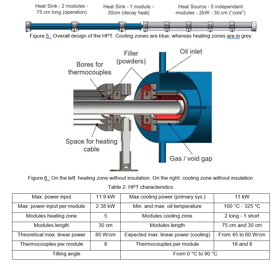
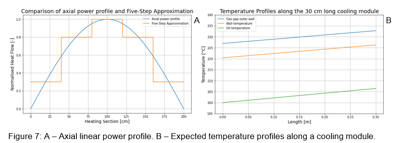
The HPT design is modularly constructed: this allows to use the HPT for heat pipes of any lengths between 40 and 400 cm and any diameter up to 38 mm. In fact, the length of any module can be adapted by cutting new pipes with a different length. Both the top and bottom attachments are always the same. Moreover, being each module controlled independently, different heat inputs can be provided (each heating module is equipped with two resistance heating cables). For instance, if the heat input profile has a cosine profile, it can be approximated by a step function with 5 steps (see Figure 7A).
In a similar manner, the cooling modules can be controlled independently. In Figure 7B, the expected temperature profile in the 30 cm long cooling module from analytical calculations can be seen where the
temperature of the inner gap wall is set constant to 800 °C. Furthermore, the linear heat flow decreases linearly from 48.18 W/cm to 47.93 W/cm, which means that around 48 W/cm can be extracted from the heat pipe. However, changing the gas composition inside the gap or the emissivity of its inner surface allow to modify both the temperature profiles and the extracted linear heat flow.
Both heating and cooling zones are insulated by multiple layers of insulating material. Ideally, all heat generated by the resistance heating cables should be transferred to the heat pipe, while all extracted heat should flow into the cooling oil. However, achieving this ideal scenario is impractical. Therefore, it is necessary to measure thermal losses accurately to obtain a precise estimation of the heat effectively transferred to and extracted from the heat pipe. This is facilitated by an outer containment structure, comprising an outer SS304 shell housing the entire setup. The containment structure serves multiple functions:
- It provides a sealed volume in which an argon atmosphere can be created, guaranteeing that no violent reactions between potassium and oxygen can take place.
- It separates the experimental set-up from the laboratory so that no chemical or dust will contaminate the laboratory hall.
- Being externally cooled it provides both a way to measure the heat removed from the system and an emergency cooling system. If the primary cooling system fails, it would be sufficient to turn off the heating system and wait until all the heat is slowly removed. On the other hand, during normal operations, water temperature is measured at the inlet and outlet of every Since the mass flow rate of the cooling water is known, the heat transferred to the system can be evaluated.
CONCLUSION
Both the design of the heat pipe prototypes and the HPT have been defined. All the needed materials for their construction have been procured and the assembly process is ongoing. The assembly procedure that included electron beam welding proved to be an efficient and reliable technique to be used for the next prototypes. The spacer proved to be extremely efficient in making the capillary stable inside the pipe. This set up make equipping the heat pipe with any kind of temperature sensor along its axis possible and simple.
The HPT design make possible to set a working temperature or a working linear heat flow, while providing a suitable cooling on the condensation side and a continuous estimation of thermal losses along the tester.
Once operative the HPT will enable to record the heat transport performances of multiple heat pipes at different working temperatures, at different tilting angles and with longer or shorter evaporation and condensation zones. In short, a wide range of experiments will be possible in which the limits of various heat pipes can be reached safely. At the same time the realization of three heat pipe prototypes will make possible to assess the efficiency of well-known wick structures in applications that require long heat pipes.
REFERENCES
- A. Gibson, S. R. Oleson, D. I. Poston and P. McClure, „NASA’s Kilopower reactor development and the path to higher power missions“, 2017 IEEE Aerospace Conference, Big Sky, MT, USA, 2017, pp. 1-14
- Arafat, Jurie Van Wyk, “eVinci Micro Reactor”, Nuclear Plant Journal, March-April 2019
- Black, D. Shropshire, K. Araújo, A. van Heek, Prospects for Nuclear Microreactors: A Review of the Technology, Economics, and Regulatory Considerations, Nuclear Technology, 209:sup1, S1-S20, (2023)
- Amir Faghri, Heat Pipe Science and Technology, Second Edition, Global Digital Press; 2nd ed. edition (25 Nov. 2016)
- Shung-Wen Kang, Huan-Ming Yeh, Meng-Chang Tsai and His-Hsiang Wu, “Manufacture and Test of a High Temperature Heat Pipe”, Journal of Applied Science and Engineering, Vol. 22, No. 3,
- 493E499 (2019)
- Zhixing Tian, Xiao Liu, Chenglong Wang, Dalin Zhang, Wenxi Tian, Suizheng Qiu, G.H. Su, “Experimental investigation on the heat transfer performance of high-temperature potassium heat pipe for nuclear reactor”, Nuclear Engineering and Design 378, (2021)
- P. Dakin, D. J. Pratt, G. W. Bibby, and J. N. Ross, “Distributed optical fibre Raman temperature sensor using a semiconductor light source and detector,” Electron. Lett. 21(13), 569–570 (1985)
- Jingyu Wu, Mohan Wang, Kehao Zhao et al., “Distributed Fiber Sensors With High Spatial Resolution in Extreme Radiation Environments in Nuclear Reactor Cores”, Journal Of Lightwave Technology, vol. 39, no. 14, July 15, 2021
ACKNOWLEDGEMENTS
The presented work was funded by the German Federal Ministry of Education and Research (BMBF, project no. 02NUK074A) on basis of a decision by the German Bundestag.
0 Comments