Marcus Trempler
Siempelkamp NIS Ingenieursgesellschaft mbh Industriestr. 13, 63755 Alzenau marcus.trempler@siempelkamp-nis.com
Detlef Queißer
Siempelkamp NIS Ingenieursgesellschaft mbh Industriestr. 13, 63755 Alzenau detlef.queisser@siempelkamp-nis.com
SUMMARY
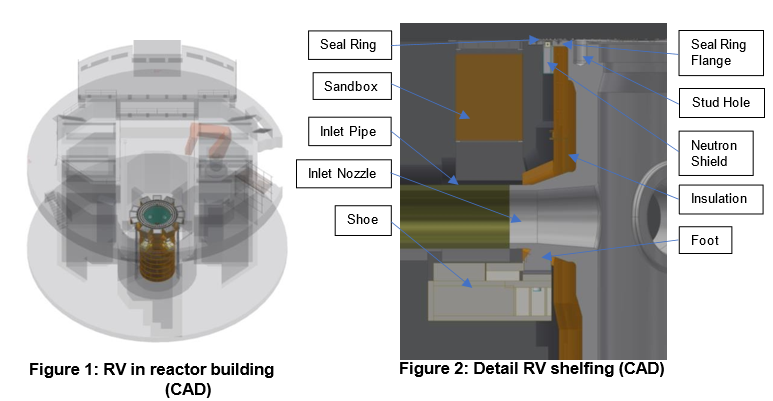
The Fort Calhoun Nuclear Generating Station (FCS) commissioned in August 1973 was shut down in October 2016. The station was powered by a pressurized water reactor with a name plate capacity of 502 MW. The station is located between Fort Calhoun and Blair in Nebraska, USA. Following the shut- down the decommissioning of the power station started. Siempelkamp NIS was tasked with the segmentation of the Reactor Vessel (RV). The RV was roughly 10 meters high and had a diameter of about 4 meters. The 203 metric ton heavy vessel was cut into 43 segments using an oxy-fuel cutting system. The paper focuses on the whole execution phase of the project.
KEYWORDS
Decommissioning Reactor Vessel Segmentation
Oxy-fuel Cutting
INTRODUCTION
Starting with the design phase in early 2021 Siempelkamp NIS developed the processes necessary for the segmentation of the RV and the attached insulation based on as-built drawings and in close collaboration with the project management of the customer on site. Furthermore, Siempelkamp NIS designed a cutting and packaging plan, shielded boxes for flange segments, a story board and a detailed schedule. Siempelkamp NIS procured the equipment needed in Europe and transported it to the United States. During the project’s execution phase a Siempelkamp NIS team was on site from January to December 2023 to lead and guide through the processes from mobilization of the equipment to the final cut. The processes necessary for segmentation of the RV were split into three major work pages.
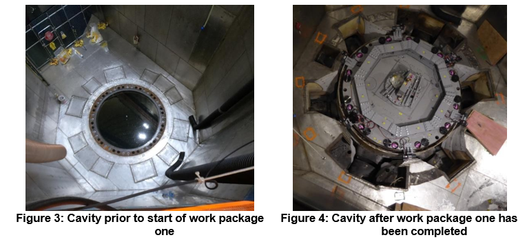
WORK PACKAGE ONE
The first package included steps that prepared the RV to be lifted out of the surrounding biological shield into the upper cavity. To understand why these steps were necessary the process to dismantle the reactor vessel and the placement of the RV inside the biological shield has to be explained. Siempelkamp NIS uses the oxy-fuel cutting process to segment reactor vessels into transportable smaller segments. This process works only with certain types of steel that have a lower kindling
temperature compared to melting temperature. The metal is heated up with a propane-oxygen flame to its kindling temperature. Is the kindling temperature reached, a high pressure oxygen stream will be directed at the desired position of the cut. The metal burns into a metal oxide and is blown out of the cutting kerf. This process does work well with reactor steel but does not work with stainless steel. Since reactor vessels are plated with stainless steel on the inside it is not possible to cut with the process from the inside to the outside. It is only possible to cut from the outside to the inside. The thin stainless-steel cladding on the inside is melted due to the high process temperature caused by the burning process of the reactor steel and is blown out with the metal oxide. At the FCS the space between the RV and the biological shield was not sufficient enough to place an oxy-fuel cutting system around the RV. Furthermore, the vessel was encapsulated by insulation panels, that were installed to increase the efficiency of the reactor and that not only decreased the space available even more but also blocked the outer circumference of the vessel from being reached by the cutting system. The decision was made to lift the reactor vessel out of the biological shield into the upper cavity to have more space available to place the oxy-fuel cutting system and to remove the attached insulation.
Once that major decision was made, steps necessary to prepare the RV for the lift were identified. Those steps formed the base frame of work package one:
- Cleaning the stud holes: The threaded stud holes were needed to attach the lifting equipment to the RV. During the dismantling and segmentation of the RV internals debris accumulated in these holes. To clean them the stud hole hand cleaning tool was used.
- Removing the seal ring: The seal ring was bolted onto the seal ring flange on the site of the RV and onto another flange at the site of the biological Bolts were removed and the seal ring was cut with the Plasma Cutting Equipment (PCE) into smaller segments and removed.
- Removing the neutron shield: The neutron shield was welded onto the stainless-steel cladding of the biological shield, that was present at the upper site of the biological shield. It was segmented and removed using the PCE.
- Opening the sandboxes and removing the content: A sandbox was positioned above each inlet and each outlet water pipe. They needed to be emptied to position the wire for subsequent applications of the Abrasive Wire Saw (AWS).
- Removing the concrete above the nozzles: Parts of the biological shield blocked the vertical lifting path of the RV at the position of the inlet and outlet nozzles. Six concrete blocks were removed using the AWS to make way for the RV lift.
- Separating the nozzles from the pipes: The AWS was used to separate the inlet and outlet nozzles from the inlet and outlet pipes.
Completed was the first work packages with steps that needed to be done to enable future tasks other than lifting:
- Cutting of the capsule holders inside the vessel with a hydraulic shear at estimated locations of the future vertical cutting kerfs.
- Removing of the seal ring flange: The most upper part of the vessel protruded the rest of the vessel to much in the radial direction and had to be pruned prior to the oxy-fuel cutting The pruned part was called seal ring flange and was due to its stainless-steel cladding cut with the PCE.
- Precutting the RV flange: The rest of the upper site of the flange was also cladded with stainless- steel that would have negative effects on the oxy-fuel Therefore, precuts with the AWS were performed in the vertical direction that allowed the oxy-fuel process to start at a location without horizontal stainless-steel cladding.
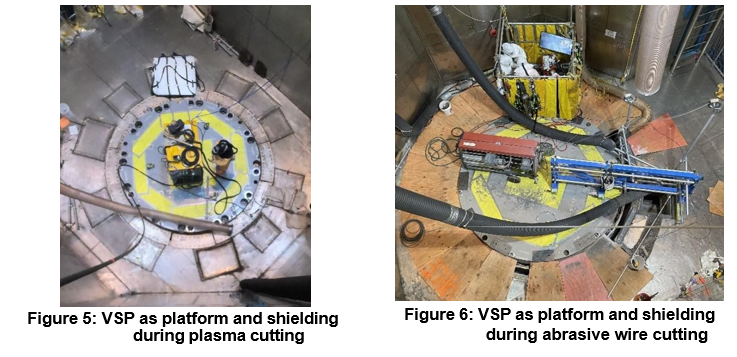
While most of the tools used during this work package one, like AWS, PCE or Hydraulic Shear were industry standard tools of the shelf, the equipment to support those tools was designed by Siempelkamp NIS particular for this project. In this paper the Vessel Shielding Plate (VSP) shall be mentioned. It is used during all the work packages. In this first work package it is as its name suggest used as a shielding plate. But it was also used as a platform that supported the work with the PCE (Figure 5) or the AWS (Figure 6).
In the second work package the VSP was used as a lifting traverse. It was bolted to the RV using the cleaned stud holes on the one hand and on the other hand it was attached to a Strand Jack System (SJS). In the third work package it was welded to the after the segmentation process leftover Hemispherical Bottom Head (HBH) to shield the surroundings from the radiation sources inside the HBH during its transportation to the waste site.
WORK PACKAGE TWO
During the second work package the RV was lifted out of the biological shield in increments. For this purpose, the RV was via the VSP attached to the SJS. The SJS was shelfed on the walls of the structure that housed the steam generators. It was not only able to lift the RV but was also able to turn it. Since the insulation was shelfed at the nozzles it came up with the RV. A major part of work package two was to remove as much insulation as possible while lifting the RV up. The insulation was made up of twelve rows of panels. With the second row from the top, the structure that shelfed the insulation on the nozzles had to be removed too. That circumstance made it necessary to install the so-called Support Structure Insulation (SSI) prior to the lifting of the RV. The SSI consisted of remote-controlled rope winches that were shelfed on the VSP, ropes that connected the winches to a frame like structure that supported the insulation at the bottom and said structure. After the removal of the second row the rest of the insulation was shelfed on the frame of the SSI at its bottom.
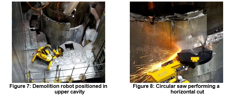
A mobile remote-controlled hydraulic demolition robot was placed in the upper cavity. After the RV was lifted by one increment of about 800 mm – 1000 mm a for the segmentation designated insulation panel (6 – 8 panels per increment) was secured with the Hydraulic Gripper (Figure 7, Figure 8) hanging down from the Portal Crane (PC) of the containment building. With the circular saw the robot performed remote-controlled vertical (Figure 8) and horizontal cuts to separate the designated panel from the rest of the insulation.
The separated panel still attached to the Hydraulic Gripper was with the help of the PC transported to a waste platform for packaging. The panels and other parts of the insulation were packaged into customized liners. For transportation to the burial site the liners were, once fully loaded, brought out of the reactor building and put into transportation containers. With a truck the package was transported to the burial site. Once unloaded and put into the final resting place the liner was filled with concrete and buried. After nine of the twelve rows of the insulation were removed, the RV was lowered down in the biological shield. The rest of the insulation (three rows and the bottom) was with the help of the remote- controlled winches lowered to the bottom of the biological shield called sump. With the cutting of the ropes that connected the rest of the insulation to the RV the first major task of work package two was finished. The dismantling and removal of the rest of the insulation was not scope of this project.
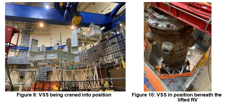
With the insulation out of the way the RV was during the second major task of work package two put into a position that enabled the oxy-fuel equipment to be installed. Therefore, the RV was lifted all the way up with the SJS. With the main hook of the PC the so-called Vessel Support Structure (VSS) was
craned beneath the RV and sat down on the same shoes the vessel once sat on prior to its lift (Figure 2). The VSS was made up of two major parts. First and foremost, it was made up of the frame that shelfed the RV at its HBH. But since this frame could not be craned directly vertically from above to its shelfing position due to the RV blocking the path, a counterweight was needed to enable the frame to be craned (hooked up off-center) beneath the RV horizontally. After the VSS was in position the RV was lowered and sat into the VSS. The RV was shelfed on six supports that were installed and part of the frame.
WORK PACKAGE THREE
The third work package started with the installation of the oxy-fuel cutting equipment, the so-called Flame Cutting Equipment (FCE). The FCE consisted of two major components. A frame and oxy-fuel cutting system that was able to move along three different axes. The frame of the FCE was made up of three twelve cornered rings that were stacked on each other forming three levels the oxy-fuel cutting system could be positioned on. On each level the cutting system could be positioned in each of the twelve corners. Flame resistant curtains were attached to each of the rings before they were lowered into the cavity with a traverse. The oxy-fuel cutting system was assembled on a platform outside the cavity. The VSP was removed and replaced with the so-called Segmentation Shielding Plate (SSP) with removable shielding segments that could be placed on two elevations. A so-called Turnable Gripper (TG) was installed to handle the oxy-fuel cutting system (Figure 11), the SSP and RV Core Segments.
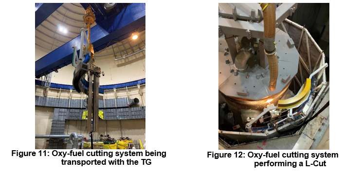
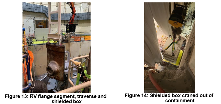
A customized traverse was installed to handle and transport the RV flange segments. The SSP as a whole was handled with the main hook of the PC. Once everything needed for the segmentation of the RV was in place the oxy-fuel cutting started with six L-Cuts in the flange part of the vessel (Figure 12) shaping the six RV flange segments and leaving them in place on small ligaments for the harvesting. To harvest a segment a shielding segment needed to be removed with the TG from the SSP. Afterwards the flange traverse was attached to the main hook of the PC and lowered into the cavity. The flange traverse connected to the RV flange segment via the pre-installed load attachment points bolted into the stud holes. The harvesting cut for the attached segment followed and the freed segment was transported to the shielded box (Figure 13). The shielded boxes for the flange segments were designed by Siempelkamp NIS. They were used for transportation (Figure 14) and for the burial of the segments. That way every other segment was removed until three flange segments were left.
The SSP that sat with its three feet on the remaining three segments was modified by bringing all the shielding plates up to second elevation. It was than repositioned by turning it 30° with the polar crane and setting down on the space the removal of the three other segments opened up. The remaining three RV Flange Segments were harvested and packaged.
During the core zone segmentation that followed the segmentation of the flange, the TG was used to move the segments to the packaging platform (Figure 15).
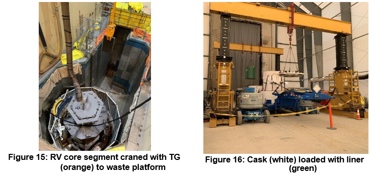
But not only the equipment to handle the segments was different, the cutting and packaging strategy also differed from the flange section. The core region was cut into three rings. Each ring was cut into twelve segments resulting in 36 RV Core Segments. Two segments were loaded into a furniture. That furniture on the other hand was loaded into one liner. The full liners were transported out of the containment and loaded into casks with heavy shielding for the transportation to the burial site (Figure 16). As the liners for the panels of the insulation the liners of the core region were unloaded at the burial site, filled with concrete and buried.
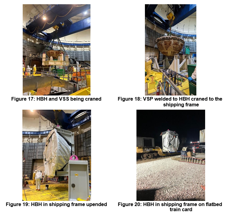
With 36 Core Zone Segments removed only the HBH was left filled with slag from the segmentation process. It was removed from the cavity with the main hook of the PC by attaching said hook to the four load attachment points located on four corners at the VSS (Figure 17). Afterwards the VSP was welded onto the HBH. Filled with grout the HBH was craned into a shipping frame (Figure 18), upended (Figure 19) and transported out of the containment. It was then placed on a flatbed train card (Figure 20) and transported to the burial site.
CONCLUSION
With the HBH removed from the cavity and placed insite the shipping frame Siempelkamp NIS’s work scope ended safe and successful. The team returned to Germany in early December 2023.
0 Comments